TITLE: Marking laser scanning targets to aid processing
DATE: 2019-07-15
AUTHOR: John L. Godlee
====================================================================
I've been processing laser scanner point cloud data I collected
with a Leica HDS6100 phase-shift Terrestrial Laser Scanner (TLS).
I've been scanning patches of woodland in southwest Angola and
wanted to generate shadowless 3D models of the woodland canopy. To
generate these models I had to record multiple scans per woodland
patch to eliminate shadows cast by tree trunks. Now I am aligning
and stitching those multiple scans back together again to form a
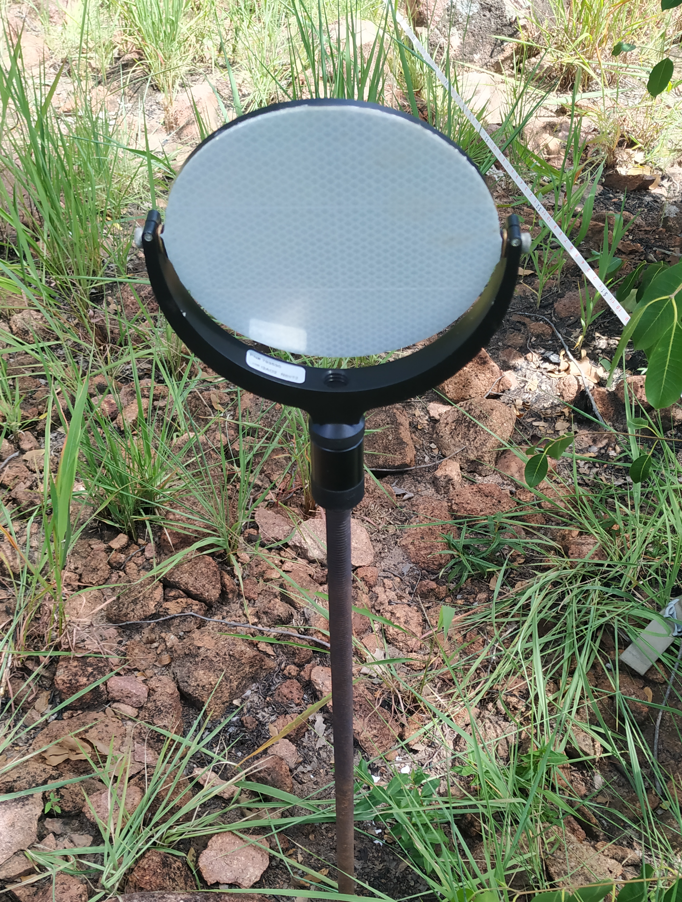
single 3D model in Leica's Cyclone software. To align the scans I
placed black and white reflective targets (Leica GZT21) in the
woodland at the time of scanning so that multiple targets could be
seen in all scans. These targets are highly reflective and can be
easily recognised in the resulting scan point cloud in the
software. The targets are given names and used to tie the scans
together, as the position of a target won't change between scans.
[Leica HDS6100 phase-shift Terrestrial Laser Scanner (TLS)]:
https://gef.nerc.ac.uk/equipment/tls/hds6100/hds6100_overview.php
[Leica's Cyclone]:
https://leica-geosystems.com/en-gb/products/laser-scanners/software/
leica-cyclone
[Leica GZT21]:
https://www.sccssurvey.co.uk/leica-gzt21-scanning-target.html
The issue I've been having is that it's not always easy to tell
which target is which on the point cloud. I tried to stick to a
consistent target layout in my circular woodland patch subplots,
with the box for the scanner always places at Target 1, with all
the other targets numbered incrementally in a clockwise direction,
like this:
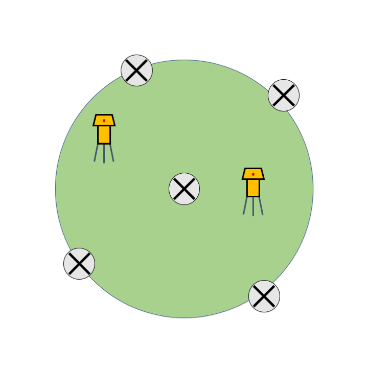
This works fine probably about 90% of the time. However, sometimes
if I make a mistake or the vegetation is particularly dense, I
can't place the targets so that all of them are visible in all the
scans. This leads to confusion in my clockwise sequence and can
lead to me mislabelling a target, resulting in the scans being
mis-aligned. Again, most of these occurrences can be rectified by
trying the next obvious target ID and running the scan registration
again, but of these 10%, about 2% I can't fix without a major
headache. It's difficult to understand 3D data on a computer screen
and the point cloud renders on Cyclone aren't the most beautiful to
look at.
As I'm planning to take the scanner out again to a different region
of southern African woodland at the end of this year, I have been
thinking about ways I could identify each target in a subplot,
rather than just the first target with the scanner box.
I always have five targets in a subplot. Four around the edge of
the subplot and one in the middle of the subplot. The middle target
is important as I also take manual measurements of tree DBH and
species which originate from this central point, therefore I need
to be able to compare the scanned model to the manual measurements.
The first target has the box, so that doesn't need to be changed,
leaving me four targets that I would like to identify in some way.
I considered marking the targets with permanent marker on the white
part of the circle, but I will have to see if this permanent marker
can be easily recognised in the scanned point cloud, which is
normally coloured according to an objects reflectance. There is
also a chance that permanent marker might damage the targets in
some way, which I should avoid, as they're ~£250 each. Leica
actually provide paper target templates as a PDF file in the
program files for Cyclone which can be edited on a computer to show
numbers or any other text, then printed, but these wouldn't be
appropriate for me because I need to be able to GNSS the targets,
meaning they have to be screwed onto a metal threaded pole.
Another possibility is to hang something off the target, a little
totem that varies in a visible way from the other four. I could
keep these totems in my pocket and just hang them off the target
arms when I go around GNSS-ing them, meaning the targets don't
always have to be used in the same order, as with the permanent
marker method.
Possible ideas for totems:
1. Circle
2. Square
3. Triangle
4. Cross
5. A
6. B
7. C
8. D
If the totem is going to hang off a string it's important that it
can be recognised regardless of whether it is upside down or back
to front, as it might swing around on the end of the string.